
















Complete Wiring Guide for Circular Connectors: Step by Step Instructions and Troubleshooting of Common Issues
Complete Wiring Guide for Circular Connectors: Step
by
Step Instructions and Troubleshooting of Common Issues
Introduction
Wiring a circular connector correctly is essential for reliable power, signal, and data transmission in industrial equipment. A poor connection can lead to intermittent signals, excessive contact resistance, equipment downtime, or even premature connector failure.
This Wiring Guide for Circular Connectors provides a practical, step‑by‑step approach to preparing wires, identifying pin assignments, terminating contacts, assembling the connector, testing the finished connection, and troubleshooting common wiring problems.
Whether you are working with an M5, M8, M9, M12, M16, or 7/8" circular connector, the same basic principle applies: always match the connector, contact, cable, and pin assignment before starting the wiring process.
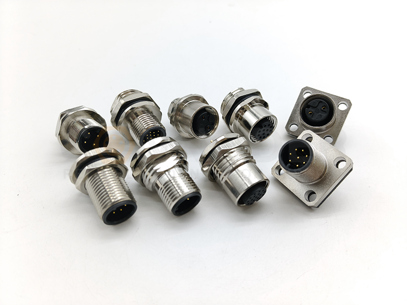
Circular Connectors
Rugged, compact and versatile — ideal when you need mixed power & signal plus environmental protection.
What Is a Circular Connector?
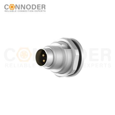
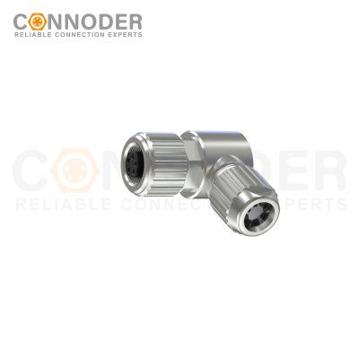
A circular connector is an electrical connector with a round housing designed to provide a detachable connection between cables, sensors, control equipment, power systems, and other electrical devices.
A typical circular connector consists of several components:
Connector housing
Insulating insert
Male pins or female sockets
Cable
Coupling mechanism
Backshell
Sealing components
Strain relief
Circular connectors are widely used in industrial automation, robotics, CNC machines, control systems, measurement equipment, communication equipment, power systems, and automated production lines.
One reason circular connectors are popular in industrial applications is their combination of compact design, mechanical strength, secure mating, and flexible contact configurations.
Why Proper Circular Connector Wiring Matters
A circular connector may look simple from the outside, but its electrical reliability depends heavily on how the wires and contacts are prepared and assembled.
Incorrect wiring can cause:
No electrical continuity
Reversed signals
Short circuits
Intermittent connections
Increased contact resistance
Localized heating
Signal interference
Cable fatigue
Loss of environmental protection
For industrial equipment, an intermittent connector problem can be particularly difficult to diagnose because the equipment may operate normally during a static test but fail when exposed to vibration, movement, temperature changes, or mechanical stress.
This is why a professional circular connector wiring guide should cover more than simply connecting wires to pins. It should include preparation, termination, assembly, testing, and troubleshooting.
What You Need Before Wiring a Circular Connector
Before starting, prepare the connector, cable, contacts, tools, and technical documentation.
Basic Tools and Materials
Depending on the connector design, you may need:
Circular connector
Matching contacts
Appropriate cable
Wire stripper
Crimping tool
Soldering iron and solder
Heat‑shrink tubing where applicable
Contact insertion/removal tools
Multimeter
Torque tool when specified
Connector datasheet or wiring diagram
The reference wiring guide also recommends preparing the appropriate contacts, wire stripper, crimping tool, soldering equipment where required, multimeter, and backshell or strain relief before assembly.
Step‑by‑Step Circular Connector Wiring Instructions
Step 1: Identify the Circular Connector
Before touching the cable, identify exactly which connector you are working with.
Check:
Connector Series
Common industrial circular connector sizes include: M5, M8, M9, M12, M16, M23, 7/8"
Pin Count
Confirm the number of contacts. For example: 3‑pin, 4‑pin, 5‑pin, 6‑pin, 8‑pin, 12‑pin
Connector Gender
Determine whether the connector is: Male / Female
Coding
For coded connectors, confirm the correct coding before wiring. This is particularly important for M12 connectors, where different coding configurations can be designed for different signal, power, fieldbus, or data applications.
Step 2: Check the Circular Connector Pinout
The pinout is one of the most important pieces of information in a wiring process.
A pinout tells you which electrical function belongs to each contact position.
For example, a connector may have contacts assigned to: Power, Ground / 0 V, Signal, Input, Output, Communication, Shielding
However, pin numbers should never be assigned based only on assumptions or wire colors.
Always check the manufacturer's technical drawing or wiring diagram for the exact connector model.
Check These Four Things Before wiring:
Pin number
Electrical function
Wire identification
Viewing direction
The fourth point is particularly important. A pinout viewed from the mating face may appear mirrored compared with the same connector viewed from the cable side.
Step 3: Select the Correct Cable and Wire Size
The cable must be compatible with the connector and the application. Consider the following factors.
Wire Gauge: The conductor cross‑section must fall within the contact's specified wire range. An undersized conductor can increase electrical losses and heating, while an oversized conductor may not fit correctly into the contact.
Current Rating: Check connector rated current, contact rating, cable ampacity, expected operating current, number of simultaneously energized contacts
Voltage Rating: Verify that the connector and cable are suitable for the system voltage.
Cable Diameter: The outer diameter of the cable must be compatible with connector housing, backshell, cable gland, sealing system, strain relief
Cable Flexibility: For robotics, moving machines, and drag‑chain applications, cable flexibility and bending performance become especially important.
Step 4: Prepare the Cable and Wires
Correct cable preparation is essential for reliable termination.
Strip the Cable Carefully
Remove the required amount of insulation using an appropriate stripping tool. Avoid cutting or nicking conductor strands. If the conductor is damaged during stripping, prepare the wire again rather than using a compromised conductor.
Check the Conductor
Inspect the wire for: Broken strands, Nicks, Oxidation, Contamination, Excessive deformation
Follow the Connector Specification
Do not use a generic stripping length simply because it worked with another connector. The correct stripping length depends on the contact and connector design.
Step 5: Choose the Correct Wiring Method
Circular connectors may use different termination methods. The most common are:
Solder termination
Crimp termination
Screw termination
Spring or push‑in termination
Factory‑terminated cable
The correct method should always follow the connector manufacturer's specification.
Solder Termination
For a solder‑type contact:
Strip the conductor.
Prepare the conductor according to the connector instructions.
Position the wire correctly.
Heat the contact appropriately.
Apply the required amount of solder.
Allow the joint to cool.
Inspect the connection.
Avoid excessive solder because it can interfere with insulation, adjacent contacts, or connector assembly.
Crimp Termination
Crimping is widely used for industrial connector contacts. The basic procedure is:
Select the correct contact.
Select the specified crimping tool.
Strip the conductor.
Insert the conductor into the contact.
Position the contact correctly in the crimp tool.
Complete the crimp.
Inspect the finished connection.
Perform an appropriate mechanical check.
The reference material emphasizes using the correct crimping tool and performing a tug test to verify that the conductor is securely attached.
What Makes a Good Crimp?
Correct wire insertion
Proper crimp height
No damaged conductor strands
Secure mechanical retention
Consistent deformation
No excessive deformation of the contact
Step 6: Insert the Contacts Into the Connector
After the wires have been terminated, insert each contact into its correct cavity.
The basic sequence is: Wire → Contact → Pin Number → Connector Cavity
Before inserting each contact, verify the pin assignment again.
Push the contact into the housing according to the connector manufacturer's instructions. Some connectors provide a mechanical click when the contact is properly seated.
The reference page also recommends matching the contacts to the correct cavities and using a removal tool when adjustment is required.
Step 7: Assemble the Connector and Strain Relief
Once the contacts are correctly positioned, complete the connector assembly.
Depending on the connector design, this may include:
Connector shell
Backshell
Cable gland
Sealing ring
O‑ring
Coupling nut
Strain relief
Why Is Strain Relief Important?
Without adequate strain relief, mechanical forces can be transferred directly to the electrical contacts.
This may result in: Broken conductors, Loose contacts, Cracked solder joints, Crimp damage, Intermittent signals
Strain relief is particularly important for connectors used in machinery subject to repeated movement or vibration.
Step 8: Secure and Mate the Connector
After assembly, check the locking mechanism.
Depending on the connector type, this may involve:
Threaded coupling
Screw locking
Push‑pull locking
Bayonet locking
Other mechanical locking systems
Do not force connectors together.
If mating is difficult, check: Connector coding, Male/female compatibility, Pin alignment, Damaged contacts, Foreign objects, Housing damage
Step 9: Test the Wired Circular Connector
Testing should be completed before the connector is connected to valuable equipment.
Continuity Test: Use a multimeter to confirm that each intended circuit is electrically continuous.
Short‑Circuit Test: Check for unintended continuity between adjacent contacts.
Polarity Test: For DC applications, verify Positive, Negative / 0 V, Ground, Signal
Insulation Testing: Where required by the application, perform an appropriate insulation‑resistance test according to the applicable product and equipment specifications.
CONNODER Circular Connector Solutions for Industrial Applications
Circular connector wiring requirements vary depending on the equipment.
CONNODER's official solution categories include applications such as:
Communication equipment
Control systems
Robotics
Measurement instruments
Power equipment
Automated production lines
CNC machine tools
Conveyor systems
For example, a robotic application may prioritize flexible cables and vibration resistance, while an automated production line may place greater emphasis on repeatable cable assemblies and secure connector mating.
This is why connector selection should begin with the application rather than simply choosing a connector based on size.
Final Takeaway
A reliable Wiring Guide for Circular Connectors should not stop at explaining where each wire goes.
Reliable connector wiring requires a complete process:
Select → Identify → Prepare → Terminate → Insert → Assemble → Secure → Test → Troubleshoot
By following the connector‑specific pinout, using the correct contact and cable size, applying the appropriate termination method, providing strain relief, and testing the completed assembly, engineers can significantly reduce wiring errors and unexpected connector failures.
For projects requiring standard or customized industrial circular connectors, CONNODER 康诺德 provides a broad range of M5, M8, M9, M12, M16, and 7/8" circular connector solutions, supported by its manufacturing, R&D, customization, and quality capabilities.
If you are developing a new industrial device or looking for a reliable circular connector and cable solution, share your required connector size, pin count, cable specification, voltage/current, application environment, and expected quantity with CONNODER. The right connector can help make the wiring process easier, more consistent, and more reliable from prototype to mass production.
CONNODER — Connecting Industrial Automation with Reliable Circular Connector Solutions.
What are the correct wiring procedures for industrial circular connectors?
First identify the connector model and pin assignment, and match the appropriate cable wire gauge. Strip cable insulation and inspect cable integrity. Crimp terminals via crimping or soldering, then insert terminals into corresponding positions by pin number. Assemble housing, sealing rings and strain‑relief components, lock the connector, and finally perform continuity, short‑circuit and polarity tests with a multimeter.
What causes high contact resistance and intermittent signals on wired circular connectors?
Primary causes include poor crimping or soldering workmanship, oxidized or contaminated contacts, incompletely seated terminals, loose connections due to missing strain relief under vibration, and damaged cable conductors. These are the most frequent wiring failures for industrial equipment under vibrating operating conditions.
What are the most common mistakes when wiring circular connectors?
Six typical pitfalls: judging pinouts solely by cable color, misreading pin diagrams from reverse sides, using mismatched terminals, applying generic crimp tools improperly, omitting strain‑relief fixation, and skipping power‑on tests. These errors can easily lead to equipment malfunctions.
For on‑site circular connector wiring, which is more reliable: crimping or soldering?
For industrial automation, vibrating machinery and robot applications, **crimped terminals** are preferred for superior mechanical stability and anti‑vibration performance against poor connections. Soldering is acceptable for low‑current static equipment; solder volume must be controlled to prevent short circuits and solder overflow jamming.
今天 15:02
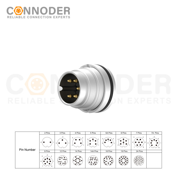
M16 6 Pin Circular Connector A-Code Interface, Waterproof Connector Receptacle Cable, Straight, Front-Locking, Unshielded
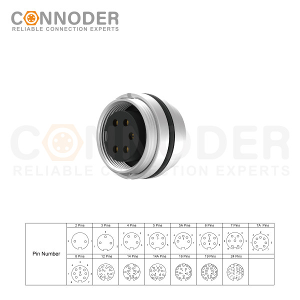
M16 6 Pin Circular Connector assemblies are ideal for demanding industrial applications such as industrial automation and aerospace, marine, and telecom systems.
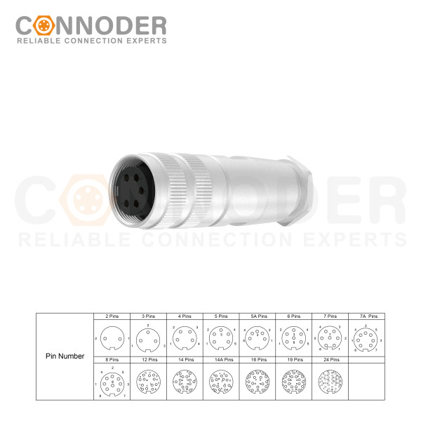
M16 6 Pin Circular Connector are ideal for demanding industrial applications such as industrial automation and aerospace, marine, and telecom systems. M16 Circular Connector are available in quick-lock wiring assembly types with IP67 protection and a vibration-resistant screw design.
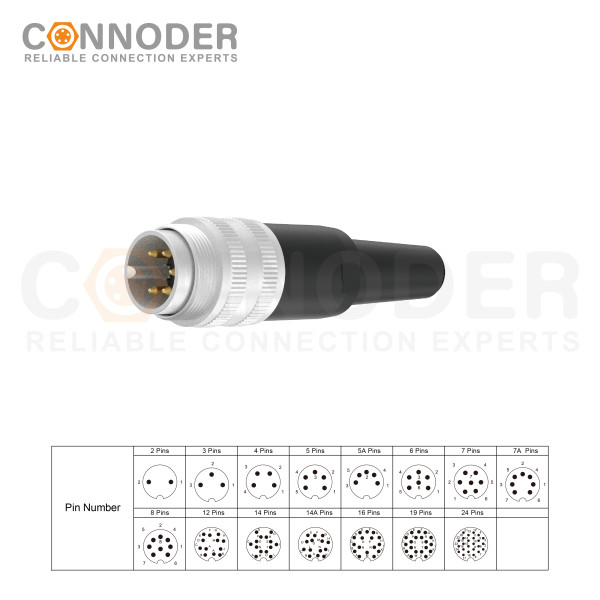
M16 6 Pin Circular Connector are ideal for demanding industrial applications such as industrial automation and aerospace, marine, and telecom systems. M16 Sensor connector are available in quick-lock wiring assembly types with IP67 protection and a vibration-resistant screw design.