












How is an integrated injection-molded circular connector manufactured?
How is an integrated injection-molded circular connector manufactured?
Introduction
An integrated molding connector combines electrical connectivity with mechanical protection in a compact, integrated structure. In many circular connector applications, injection molding is used to form the connector housing, protect the cable-to-connector interface, and provide strain relief.
But how is an integrated injection-molded circular connector manufactured? The answer involves several interconnected manufacturing stages, including connector engineering, material selection, contact manufacturing, mold development, component positioning, injection molding, cooling, demolding, inspection, and final testing.
For industrial applications, the molding process is particularly important because the finished connector may need to withstand water, dust, vibration, repeated cable movement, temperature changes, and other demanding conditions.
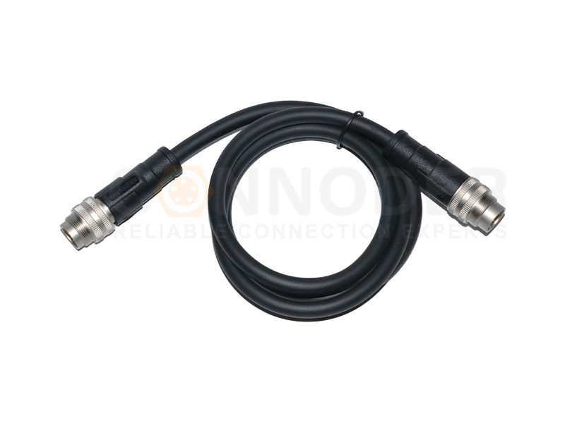
Circular Connectors
Rugged, compact and versatile — ideal when you need mixed power & signal plus environmental protection.
What Is an Integrated Molding Connector?
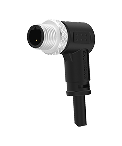
An integrated molding connector is a connector assembly in which connector components, insulation structures, cable interfaces, or protective sections are integrated through a molding process.
Depending on the design, an integrated molding connector may provide:
Connector housing protection
Electrical insulation
Cable strain relief
Mechanical reinforcement
Environmental sealing
Protection against bending and vibration
A compact connector-to-cable transition
The technology is closely related to terms such as injection-molded connector, overmolded connector, molded circular connector, and pre-molded cable assembly.
Key point: The exact construction depends on the connector type and application. An M8 sensor connector may require a different molding structure from an M12 industrial Ethernet or power connector.
How Is an Integrated Injection-Molded Circular Connector Manufactured?
Although the exact process varies according to connector construction and customer requirements, a typical manufacturing workflow can be summarized as:
Design → Material Selection → Contact Manufacturing → Mold Development → Component Positioning → Injection Molding → Cooling → Demolding → Inspection → Testing → Final Quality Control
Step 1: Product Design and Engineering
The process begins with engineering design. Before manufacturing starts, engineers need to establish the electrical, mechanical, dimensional, and environmental requirements of the connector.
Typical specifications include:
Connector size
Number of contacts
Pin configuration
Rated voltage and current
Cable diameter and material
Operating temperature
IP protection requirements
Locking mechanism
Mounting configuration
Required mating cycles
For an integrated molding connector, engineers also need to consider the molding process itself. The design should determine how the polymer will flow around the connector, how components will be held in place, where the injection point should be located, and how the finished part can be removed from the mold.
Step 2: Material Selection
Material selection directly influences the performance and manufacturability of an integrated molding connector.
Contact Materials
Circular connector contacts are commonly manufactured from conductive copper alloys. Depending on the electrical and environmental requirements, contact surfaces may receive plating such as gold, nickel, or tin.
The purpose of plating can include improving electrical contact stability, corrosion resistance, wear resistance, and mating durability.
Molding Materials
The polymer used for the molded structure must be compatible with the connector's operating environment.
Important characteristics may include:
Electrical insulation
Mechanical strength
Flexibility
Temperature resistance
Chemical resistance
Moisture resistance
Injection molding characteristics
Step 3: Contact Manufacturing and Preparation
The electrical contacts are manufactured before the molding process. Depending on the design, manufacturers may use precision stamping, forming, turning, or other metal-processing techniques.
Dimensional accuracy is critical because the contacts must maintain their specified positions after molding. Important characteristics include contact dimensions, pin alignment, contact spacing, contact force, surface finish, and plating thickness.
After production and surface treatment, the contacts are inspected before being transferred to the next manufacturing stage.
Step 4: Injection Mold Development
The injection mold determines the geometry and dimensional accuracy of the molded connector.
A typical mold includes:
Mold cavity
Core
Injection gate
Runner system
Venting structure
Cooling channels
Component positioning features
Ejection mechanism
The mold must hold the connector components securely during injection while allowing the polymer to flow around the required areas. Poor mold design can contribute to incomplete filling, flash, uneven wall thickness, air entrapment, deformation, dimensional variation, and difficulty during demolding.
Step 5: Positioning the Connector and Cable
Before injection, the connector components and cable assembly are accurately positioned inside the mold. This stage is especially important for a pre-molded cable assembly.
The connector must remain correctly aligned while molten polymer is injected under pressure. Manufacturers may use dedicated fixtures or positioning structures to control connector orientation, contact position, cable location, molded wall thickness, and strain-relief geometry.
Step 6: Injection Molding
Injection molding is the central stage of the process. The selected polymer is heated to its processing temperature and injected into the prepared mold cavity under controlled conditions.
Material Preparation → Heating → Injection → Mold Filling → Pressure Holding → Cooling → Solidification
Step 7: Cooling and Solidification
After the cavity has been filled, the molded material needs to cool and solidify. Cooling is an important part of the molding cycle because uncontrolled cooling can lead to shrinkage, warpage, dimensional variation, internal stress, and surface defects.
A well-designed mold uses appropriate cooling structures to help maintain dimensional consistency. The connector should remain sufficiently stable before the mold is opened and the finished product is removed.
Step 8: Demolding and Trimming
Once the molded material has solidified, the mold is opened and the connector is removed. The finished part is then visually inspected.
Depending on the mold and product design, additional operations may include:
Flash removal
Gate trimming
Surface cleaning
Cable inspection
Connector orientation inspection
Step 9: Electrical, Mechanical, and Environmental Testing
A visually perfect molded connector is not necessarily a reliable connector. Testing is therefore an essential part of integrated molding connector manufacturing.
Electrical Testing
Electrical continuity
Contact resistance
Insulation resistance
Dielectric withstand
Signal transmission performance where applicable
Mechanical Testing
Cable pull-out
Mating and unmating force
Mating-cycle durability
Vibration resistance
Cable bending
Connector retention
Environmental Testing
Water ingress
IP protection
Temperature cycling
Humidity
Corrosion
Chemical exposure where applicable
Step 10: Final Quality Control
After manufacturing and testing, the connector undergoes final quality inspection.
Typical inspection points include:
Connector dimensions
Pin configuration
Cable length
Connector orientation
Molded appearance
Electrical performance
Mechanical performance
Environmental protection requirements
For customized orders, final inspection should also verify that the finished product matches the customer's approved drawings and specifications.
Integrated Molding Connector vs. Conventional Connector Assembly
| Factor | Integrated Molding Connector | Conventional Connector Assembly |
|---|---|---|
| Connector-to-cable integration | Integrated | Often assembled separately |
| Strain relief | Molded structure | May use separate components |
| Field assembly | Can be reduced | May be required |
| Environmental protection | Can be integrated into design | Depends on sealing structure |
| Cable length customization | Available | Available |
| Production consistency | High with controlled tooling | Depends on assembly process |
| Maintenance | Depends on design | Potentially easier to replace individual components |
Where Are Integrated Molding Connectors Used?
Industrial Automation
Molded M8 and M12 connectors can be used with sensors, actuators, control systems, and automation equipment.
Robotics
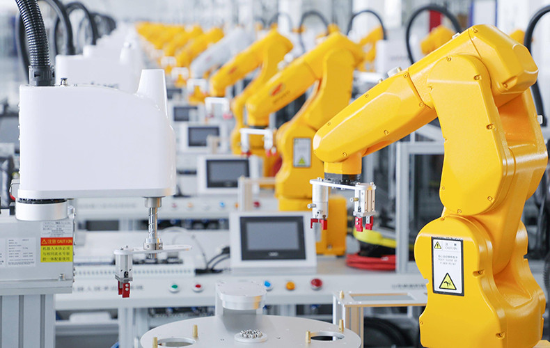
Robotic equipment can expose cables and connectors to repeated movement, vibration, and bending.
Industrial Ethernet
M12 molded cable assemblies can be used in industrial communication systems where reliable connectivity and environmental protection are important.
Sensors and Instrumentation
Smaller circular connector families such as M5, M8, and M9 can be used where installation space is limited.
Machinery and Transportation
Integrated cable assemblies can help simplify installation while providing mechanical protection at the connector-to-cable interface.
What Should You Ask an Integrated Molding Connector Manufacturer?
Does the manufacturer have its own injection molding capability?
Can the supplier develop customized molds?
Which molding materials are available?
Can the connector and cable be supplied as a pre-molded assembly?
What IP protection levels are available?
What electrical and mechanical tests are performed?
Can the supplier customize cable length and connector configuration?
Can the manufacturer provide prototypes before mass production?
What quality management system is used?
Can the supplier support long-term production and repeat orders?
What is an integrated molding connector?
An integrated molding connector is a connector assembly in which selected connector, cable, insulation, or protective components are integrated through an injection molding process. This structure can provide electrical insulation, mechanical protection, cable strain relief, and environmental protection.
How is an integrated injection-molded circular connector manufactured?
The typical manufacturing process includes product design, material selection, contact manufacturing, mold development, component positioning, injection molding, cooling, demolding, trimming, electrical and mechanical testing, and final quality inspection.
What materials are commonly used for injection-molded circular connectors?
Conductive contacts are commonly made from copper alloys with suitable surface plating, while the molded housing or cable jacket may use materials such as PVC, PUR, TPU, or other engineering thermoplastics selected according to the application's electrical, mechanical, and environmental requirements.
What are the advantages of an integrated molding connector?
An integrated molding connector can provide improved cable strain relief, a compact connector-to-cable structure, consistent production quality, reduced assembly steps, and protection against environmental factors such as moisture, dust, vibration, and mechanical stress.
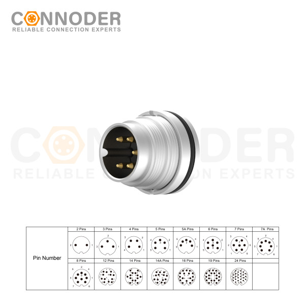
M16 6 Pin Circular Connector A-Code Interface, Waterproof Connector Receptacle Cable, Straight, Front-Locking, Unshielded
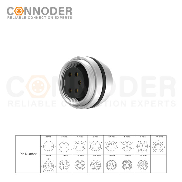
M16 6 Pin Circular Connector assemblies are ideal for demanding industrial applications such as industrial automation and aerospace, marine, and telecom systems.
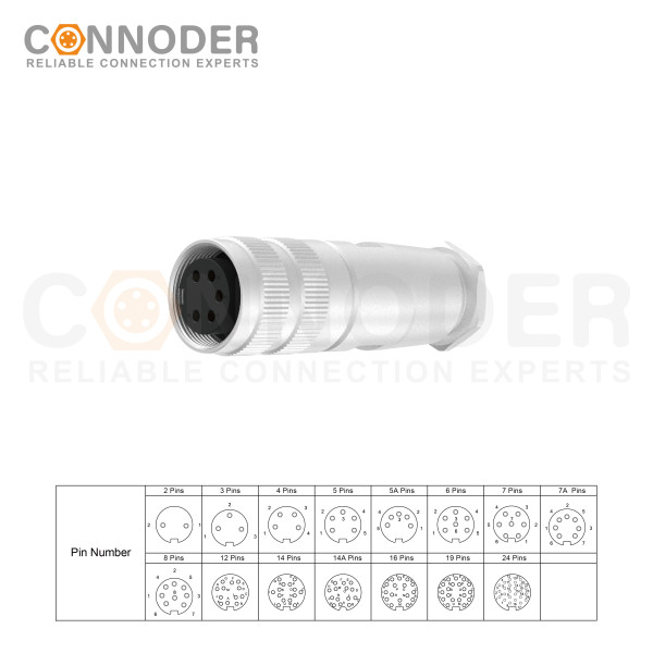
M16 6 Pin Circular Connector are ideal for demanding industrial applications such as industrial automation and aerospace, marine, and telecom systems. M16 Circular Connector are available in quick-lock wiring assembly types with IP67 protection and a vibration-resistant screw design.
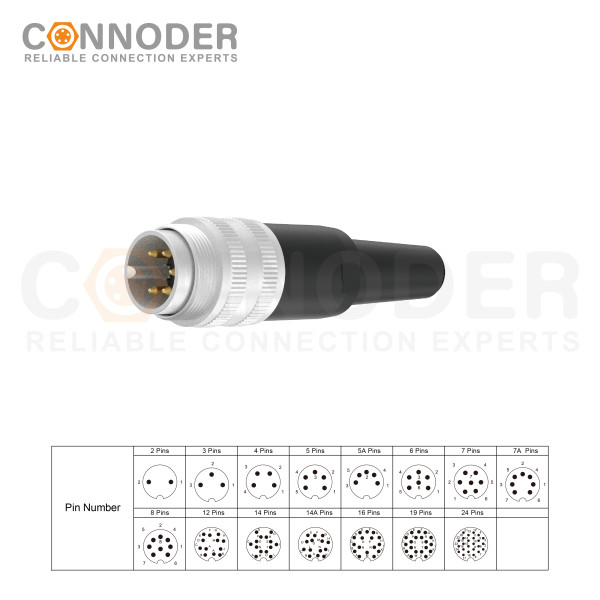
M16 6 Pin Circular Connector are ideal for demanding industrial applications such as industrial automation and aerospace, marine, and telecom systems. M16 Sensor connector are available in quick-lock wiring assembly types with IP67 protection and a vibration-resistant screw design.