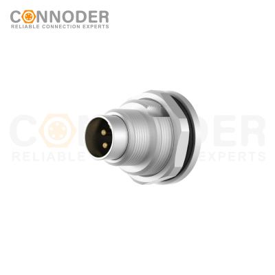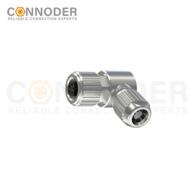













What is the basic structure of the M-series circular connector?
What is the basic structure of the M-series circular connector?
Introduction
When engineers evaluate M Series Circular Connectors, they often focus first on connector size, pin count, IP rating, or coding. However, understanding the basic connector structure is equally important.
So, what is the basic structure of the M-series circular connector? An M Series circular connector is generally built around the shell, insulator, and contact body, with additional components such as coupling nuts, sealing elements, cable glands, strain reliefs, mounting hardware, and coding features completing the connection system.
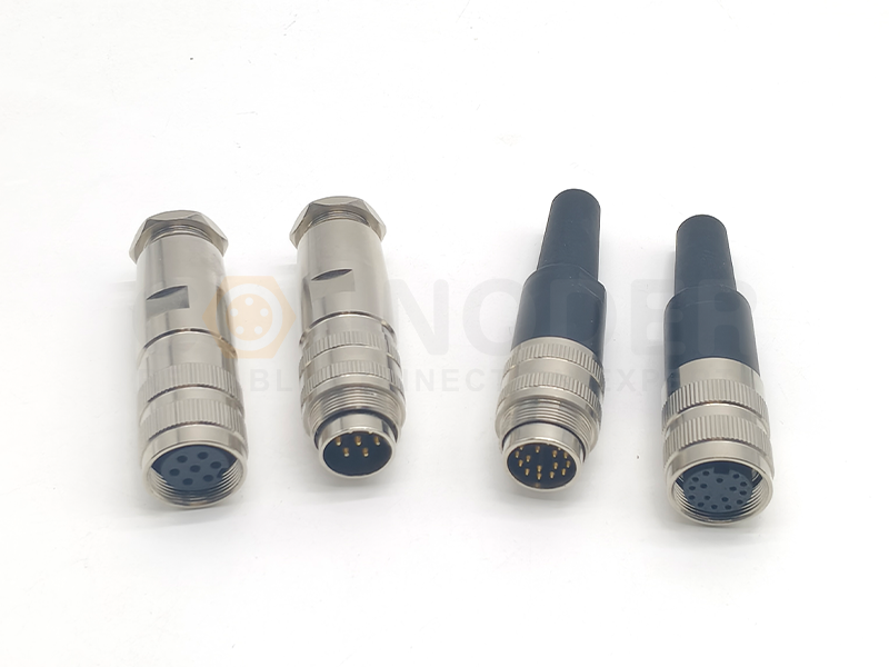
Circular Connectors
Rugged, compact and versatile — ideal when you need mixed power & signal plus environmental protection.
What Are M Series Circular Connectors?
M Series Circular Connectors are a family of compact circular connectors commonly used in industrial electrical and electronic equipment.
The “M” designation generally refers to the metric thread system used by the connector. Common sizes include M5, M8, M9, M12, M16, and M23 and larger industrial connector families. Different M Series sizes are designed for different combinations of installation space, contact count, electrical requirements, mechanical strength, and environmental protection.
Compact M5 and M8 connectors can be suitable for miniature sensors and space-constrained equipment, while M12 connectors are widely used for sensors, actuators, automation systems, industrial communication, and Ethernet applications. Larger connector sizes can provide additional space for contacts and more demanding mechanical or electrical requirements.
What Is the Basic Structure of an M Series Circular Connector?
A typical M Series circular connector can be understood through seven core components:
Shell or Housing
Insulator
Contact Body
Coupling and Locking Mechanism
Sealing Components
Cable Termination and Strain Relief
Coding and Keying Features
The first three components form the fundamental structure of the connector, while the remaining components provide mechanical security, environmental protection, installation flexibility, and application-specific functionality.
1. Shell or Housing: The Mechanical Foundation
The shell, also called the housing, is the outer body of an M Series circular connector. It provides the mechanical foundation for the connector and protects internal electrical components from external forces.
Main functions include:
Protecting internal contacts
Supporting the insulating insert
Maintaining connector alignment
Providing mechanical strength
Supporting the coupling mechanism
Providing mounting interfaces
Contributing to environmental protection
Providing shielding in suitable metal connector designs
Plastic housings can provide low weight, electrical insulation, corrosion resistance, and cost efficiency. Metal housings may be preferred when mechanical robustness, durability, or electromagnetic shielding is important.
2. Insulator: Keeping Contacts Electrically Separated
The insulator is located inside the connector housing and holds the electrical contacts in their designed positions. Its main purpose is to maintain electrical isolation between individual contacts and between the contacts and the connector housing.
Key functions include:
Holding pins and sockets in position
Maintaining contact spacing
Preventing accidental electrical contact
Providing electrical insulation
Supporting connector geometry
Contributing to environmental sealing in suitable designs
The insulating material must maintain its physical dimensions and electrical properties under the connector’s specified operating conditions, including temperature changes, vibration, humidity, electrical stress, and repeated mating cycles.
3. Contact Body: The Electrical Core
The contact body is responsible for establishing the actual electrical connection. It typically consists of male pins, female sockets, or other mating contact elements.
Important contact characteristics include:
Contact resistance
Current-carrying capability
Voltage rating
Contact material
Surface plating
Corrosion resistance
Mating durability
Signal integrity
Depending on the connector design, contacts may be connected to cables using solder, crimp, screw, PCB, overmolded, or field-wireable termination technologies.
4. Coupling and Locking Mechanism
Electrical contacts alone cannot guarantee a reliable industrial connection. The connector must also remain mechanically secure after mating. The coupling mechanism connects the plug and receptacle and maintains the required mating force.
Many M Series Circular Connectors use threaded coupling systems, while specific connector families may use other locking technologies. A reliable coupling system helps prevent unintended separation caused by vibration, shock, cable movement, machine operation, and mechanical stress.
5. Sealing Components: Protecting the Connection
Many M Series Circular Connectors are designed for demanding environments where moisture, dust, oil, or other contaminants may affect electrical performance. This makes the sealing system an important part of the connector structure.
Typical sealing elements may include:
O-rings
Interface seals
Cable seals
Gaskets
Rear sealing components
6. Cable Termination and Strain Relief
The rear portion of an M Series connector provides the connection between the electrical contacts and the external cable. The termination method can significantly affect assembly efficiency and long-term reliability.
Common termination methods include:
Solder: Suitable for certain cable assemblies and connector designs.
Crimp: Provides a mechanically stable electrical connection and is widely used in cable assembly production.
Screw: Useful for field installation and serviceable connector designs.
PCB Mounting: Integrates the connector directly with a circuit board or electronic device.
Overmolded Cable: Provides a factory-assembled connector and cable solution with integrated mechanical protection.
A properly designed strain-relief structure helps reduce mechanical stress caused by repeated bending, pulling, twisting, vibration, and machine movement.
7. Coding and Keying: Preventing Incorrect Connections
The physical structure of an M Series Circular Connector also includes coding or keying features. Coding helps prevent incorrect mating between connectors intended for different electrical or communication functions.
Why Choose CONNODER for M Series Circular Connectors?
For companies sourcing M Series Circular Connectors, choosing the right manufacturer can be just as important as selecting the correct connector size.
CONNODER specializes in the research, development, and manufacturing of industrial circular connector solutions. Its product range covers multiple industrial connector sizes and configurations, including M5, M8, M9, M12, and M16 circular connectors, supporting different equipment requirements.
CONNODER's manufacturing capabilities support the development and production of industrial connector products, while its engineering-oriented approach allows customers to discuss connector specifications, customization requirements, and application conditions directly with a professional connector manufacturer.
CONNODER M Series Product Capabilities
Multiple M Series sizes
Different pin configurations
Straight and right-angle designs
Cable and panel-mount configurations
Different termination methods
Waterproof industrial connector solutions
Custom connector configurations
Industrial automation applications
Application-oriented technical support
Conclusion
Understanding the structure of M Series Circular Connectors is the first step toward making a reliable connector selection.
The shell provides mechanical protection. The insulator maintains electrical isolation. The contact body establishes the electrical path. The coupling system keeps the connector securely mated, while sealing and strain-relief components help the complete assembly withstand environmental and mechanical conditions.
Because the exact structure can vary between M5, M8, M9, M12, M16, and other M Series connector configurations, engineers should evaluate connector size together with pin count, coding, termination method, electrical specifications, IP protection, materials, mounting configuration, cable requirements, and operating environment.
What is the basic structure of an M Series circular connector?
An M Series circular connector typically consists of a shell or housing, insulating insert, contact body, coupling mechanism, sealing components, and cable termination or strain relief. These components work together to provide electrical connectivity, mechanical protection, and environmental resistance.
What are the main components of an M Series circular connector?
The main components include the shell, insulator, electrical contacts, coupling mechanism, sealing elements, and cable termination system. Coding and keying features may also be incorporated depending on the connector type and application.
What is the difference between M8 and M12 circular connectors?
M8 connectors are generally more compact and are commonly used for sensors and space-constrained automation equipment. M12 connectors offer a larger platform with more configuration and coding options and are widely used for sensors, actuators, industrial Ethernet, fieldbus, and automation systems.
Are M Series circular connectors waterproof?
Some M Series circular connectors are designed with IP-rated sealing systems for protection against dust and water. However, waterproof performance depends on the specific connector design, sealing structure, cable assembly, mating condition, and specified IP rating.
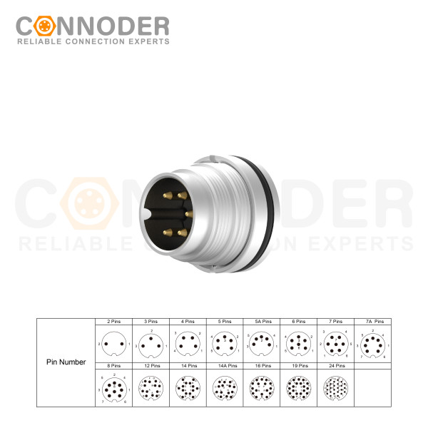
M16 6 Pin Circular Connector A-Code Interface, Waterproof Connector Receptacle Cable, Straight, Front-Locking, Unshielded
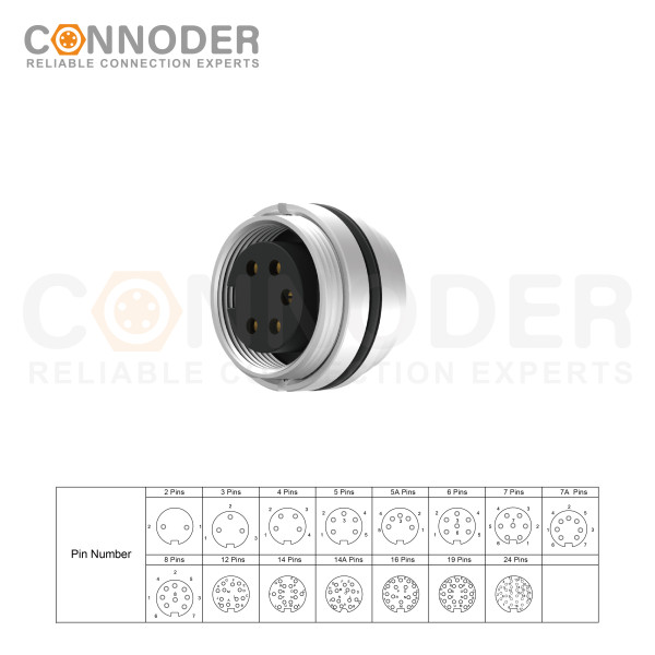
M16 6 Pin Circular Connector assemblies are ideal for demanding industrial applications such as industrial automation and aerospace, marine, and telecom systems.
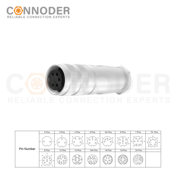
M16 6 Pin Circular Connector are ideal for demanding industrial applications such as industrial automation and aerospace, marine, and telecom systems. M16 Circular Connector are available in quick-lock wiring assembly types with IP67 protection and a vibration-resistant screw design.
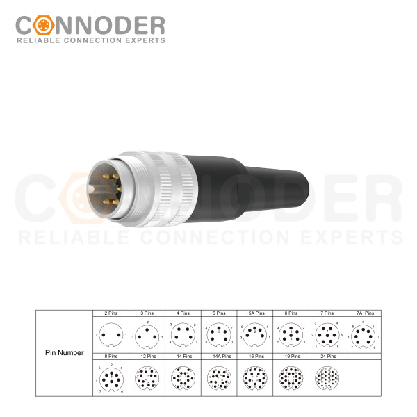
M16 6 Pin Circular Connector are ideal for demanding industrial applications such as industrial automation and aerospace, marine, and telecom systems. M16 Sensor connector are available in quick-lock wiring assembly types with IP67 protection and a vibration-resistant screw design.