
















What is the shielding principle of the M series circular connectors?
What is the shielding principle of the M series circular connectors?
Introduction
In modern industrial automation, reliable electrical connections are essential for accurate signal transmission, stable communication, and equipment performance. Motors, variable-frequency drives, switching power supplies, and industrial communication systems can generate electromagnetic interference (EMI), potentially affecting sensitive electrical signals. Understanding the shielding principle of the connector helps engineers select suitable circular connectors for demanding industrial environments.
M series circular connectors, including M5, M8, M12, and M16 types, are widely used in sensors, actuators, industrial control equipment, and data communication systems. Depending on their construction, shielded versions can help reduce electromagnetic coupling by combining conductive connector shells, compatible cable shields, and properly designed shield termination.
This guide explains the shielding mechanism of M series circular connectors, compares shielded and unshielded designs, and outlines practical selection considerations. It also introduces CONNODER , a manufacturer of industrial circular connectors and connectivity solutions.
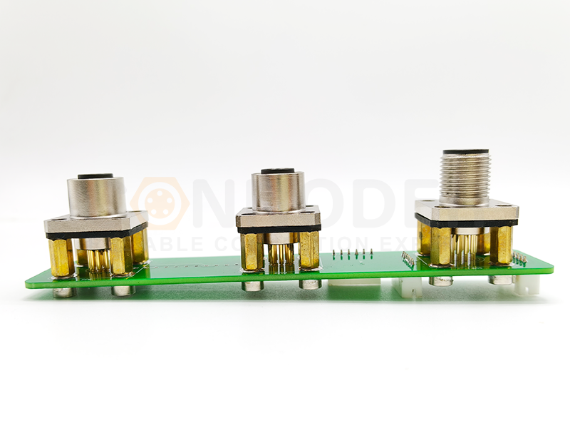
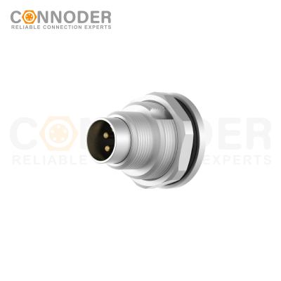
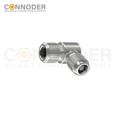
Circular Connectors
Rugged, compact and versatile — ideal when you need mixed power & signal plus environmental protection.
What Is the Shielding Principle of the Connector?
The shielding principle of the connector refers to the use of conductive structures and an appropriate electrical shielding path to reduce unwanted electromagnetic coupling between electrical circuits and their surrounding environment.
Electromagnetic interference can enter a system through radiated fields or unwanted electrical coupling. If interference reaches sensitive signal conductors, it may cause communication errors, unstable sensor readings, or degraded signal quality. A properly designed shielded connector helps control these effects through several related mechanisms.
1.Electromagnetic Reflection and Absorption
Conductive shielding structures can reflect part of an incident electromagnetic field. Depending on the material, thickness, frequency, and field characteristics, some energy may also be absorbed and dissipated within the shield. Actual shielding effectiveness depends on the complete design rather than the material alone.
2.A Continuous Conductive Shield Path
The cable shield should connect appropriately to the connector's conductive structure. When the connector mates with a compatible receptacle, the conductive interfaces should maintain continuity if the system is designed for continuous shielding. This helps control unwanted electromagnetic coupling across the cable-to-connector transition and mating interface.
3.Reduced Electromagnetic Coupling
A continuous shield can reduce the amount of external electromagnetic energy coupled into internal signal conductors. It can also help contain electromagnetic emissions generated by connected equipment. Performance depends on the cable, connector construction, operating frequency, installation, and equipment bonding.
Key principle: Effective connector shielding requires a suitable conductive structure and a well-designed shield path across the entire connection system. A metal housing alone does not guarantee effective EMI protection.
How Does Shielding Work in M Series Circular Connectors?
M series circular connectors are designed for a wide range of industrial applications. Their compact dimensions, circular interfaces, and threaded coupling mechanisms make them useful where secure electrical connections are required. Not every M series connector is shielded; the availability and effectiveness of shielding depend on the specific product design.
Conductive Metal Shell
The connector shell provides a conductive enclosure around the mating interface. Depending on the design, it may be manufactured from nickel-plated brass, stainless steel, or another conductive material. The shell can help control electromagnetic coupling and provide a contact surface for the cable shield and mating connector.
Cable Shield
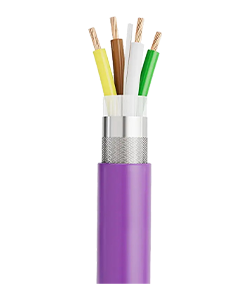
Industrial cables may use braided shields, foil shields, or combinations of both. These structures help reduce electromagnetic coupling between internal conductors and the external environment. The connector must be compatible with the cable's outer diameter and shield construction to support reliable termination.
Shield Termination
Shield termination establishes the electrical connection between the cable shield and the connector's conductive structure. A properly designed circumferential termination can help maintain continuity and reduce discontinuities at the cable-to-connector transition.
Mating Interface and Chassis Bonding
For a shielded connection, the plug and receptacle shells must provide the intended electrical continuity when mated. The connector may also be bonded to the equipment chassis or panel as part of the overall EMC design. Poor contact, corrosion, unsuitable mounting arrangements, or incorrect assembly can compromise the intended shielding path.
Shielded vs. Unshielded M Series Circular Connectors
Shielded and unshielded circular connectors serve different application requirements. The correct choice depends on the electromagnetic environment, signal sensitivity, cable construction, installation conditions, and applicable system specifications.
| Feature | Shielded Connector | Unshielded Connector |
|---|---|---|
| Shield construction | Designed with a conductive shielding path | Does not provide a complete connector shield path |
| EMI protection | Can reduce electromagnetic coupling when correctly implemented | Generally offers less shielding against external EMI |
| Signal integrity | Can improve noise immunity in suitable applications | May be sufficient in low-noise environments |
| Installation | Requires appropriate shield termination and bonding | Often simpler when no shield connection is required |
| Cost and complexity | May involve additional components and assembly steps | Often more economical |
| Typical applications | Industrial Ethernet, noise-sensitive signals, electrically noisy environments | Basic sensors, simple I/O, and applications without stringent shielding requirements |
When Should You Choose a Shielded Connector?
Consider shielded connectors when cables run near motors, servo drives, inverters, or switching power supplies; when high-speed communication is involved; or when the system has defined EMC requirements.
When Can an Unshielded Connector Be Appropriate?
Unshielded connectors may be suitable for basic sensor connections and simple control circuits in electrically quiet environments, provided the application requirements permit their use. The decision should be based on actual operating conditions rather than price alone.
What Factors Affect Connector Shielding Effectiveness?
The performance of a shielded connector depends on multiple factors.
Shell material and surface condition: Conductivity, shell geometry, surface finish, corrosion, and mechanical wear influence electrical continuity and shielding behavior.
Shield continuity: The cable shield, termination, connector shell, mating interface, and intended chassis-bonding point must form the designed electrical path.
Operating frequency: Shielding performance changes with frequency because of parasitic inductance, capacitance, and structural discontinuities.
Cable construction: Foil and braided shields have different electrical and mechanical properties. Cable diameter and termination compatibility are also important.
Grounding and bonding: The connector shell and cable shield should be integrated into the equipment's EMC strategy. The appropriate arrangement depends on system architecture and applicable requirements.
Installation quality: Poor cable preparation, loose coupling interfaces, corrosion, damaged contacts, and incorrect assembly can reduce performance.
For critical applications, review product specifications and test results for the complete cable-and-connector system.
How to Select the Right Shielded Circular Connector
Before selecting a shielded M series connector, engineers and purchasing teams should evaluate the following requirements.
Application type: Determine whether the connector will be used for sensors, control signals, industrial Ethernet, or power.
EMI environment: Identify nearby motors, inverters, switching supplies, and other potential interference sources.
Connector size: Select M5, M8, M12, or M16 based on space, contact configuration, and electrical requirements.
Shielding design: Confirm that the product provides the required conductive shell and shield termination.
Cable compatibility: Check cable diameter, braid or foil construction, and assembly requirements.
Environmental protection: Evaluate the required IP rating, temperature range, vibration resistance, and chemical exposure.
Documentation and testing: Review product drawings, technical specifications, EMC evidence, and relevant compliance requirements.
Customization: Determine whether special pin counts, cable lengths, materials, or mounting styles are necessary.
A connector should be selected according to the complete application specification, not simply by its size or external appearance.
Conclusion
The shielding principle of the connector is based on creating an effective conductive barrier and maintaining a suitable shielding path throughout the connection system. For M series circular connectors, performance depends on the interaction between the connector shell, cable shield, termination method, mating interface, and equipment bonding.
By understanding these factors, engineers can make more informed decisions when selecting shielded M5, M8, M12, and M16 connectors for industrial automation and communication applications.
CONNODER offers a range of industrial circular connector solutions to support different application requirements. By confirming product-specific shielding capabilities and matching connector configurations to real operating conditions, customers can work toward reliable, application-appropriate connectivity.
What is the shielding principle of the connector?
The shielding principle of the connector uses conductive structures and a properly designed shielding path to reduce electromagnetic interference (EMI). In shielded circular connectors, the metal shell, cable shield, and shield termination work together to help protect signal integrity.
How does shielding work in M series circular connectors?
Shielding in M series circular connectors typically relies on a conductive connector shell, a compatible cable shield, and reliable electrical continuity across the termination and mating interfaces. When properly designed and installed, this structure can reduce unwanted electromagnetic coupling in industrial applications.
Why is 360-degree shielding important for circular connectors?
360-degree shielding creates circumferential electrical contact between the cable shield and connector shell. It helps maintain shield continuity and can reduce high-frequency impedance discontinuities compared with a long, narrow pigtail connection.
What is the difference between shielded and unshielded M12 connectors?
Shielded M12 connectors incorporate a designed conductive shielding path that can help reduce electromagnetic interference when correctly installed. Unshielded M12 connectors may be suitable for applications with lower interference levels and less demanding EMC requirements. The best choice depends on the operating environment and system specifications.
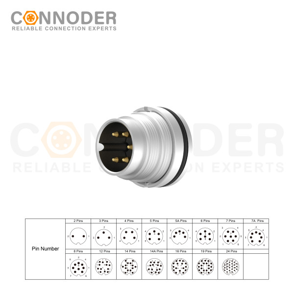
M16 6 Pin Circular Connector A-Code Interface, Waterproof Connector Receptacle Cable, Straight, Front-Locking, Unshielded
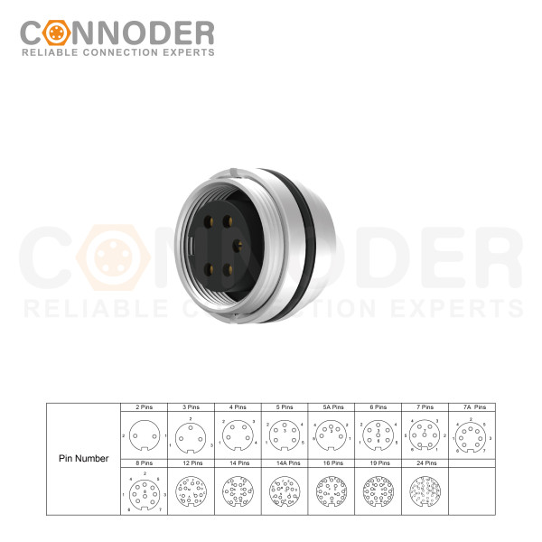
M16 6 Pin Circular Connector assemblies are ideal for demanding industrial applications such as industrial automation and aerospace, marine, and telecom systems.
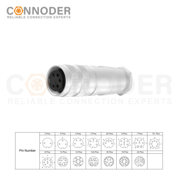
M16 6 Pin Circular Connector are ideal for demanding industrial applications such as industrial automation and aerospace, marine, and telecom systems. M16 Circular Connector are available in quick-lock wiring assembly types with IP67 protection and a vibration-resistant screw design.
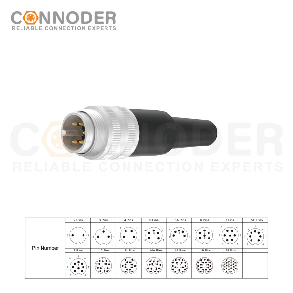
M16 6 Pin Circular Connector are ideal for demanding industrial applications such as industrial automation and aerospace, marine, and telecom systems. M16 Sensor connector are available in quick-lock wiring assembly types with IP67 protection and a vibration-resistant screw design.